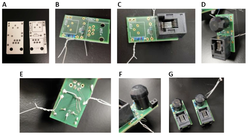
Figure 2. Assembly of the PIR sensor units.
(A) Image of the PIR circuit board prior to addition of components. (B) Addition of the 1 k and 10 k Ohm Resistors to the board. (C) Addition of the RJ12 jack to the board. (D) Addition of the PIR module to the board. (E) Twisting wires and bending of legs will secure components prior to soldering. (F) Addition of a 2-pin header to the board for LDR connection. (G) Final assembly of PIR sensor units both with (right) and without (left) an LDR.

