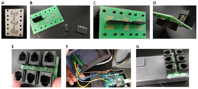
Figure 3. Assembly of the main board.
(A) Image of the main circuit board prior to addition of components. (B) Headers to be mounted to the underside of the main board. (C) Headers mounted to the underside of the board. (D) RJ12 connectors to be mounted to the main board. (E) Addition of RJ12 connectors to the main board. (F) Addition wiring connections between the Arduino Uno microcontroller (lower case section) and the headers on the underside of the main board (upper case section). (G) Final assembly of the main board on the Arduino case.

