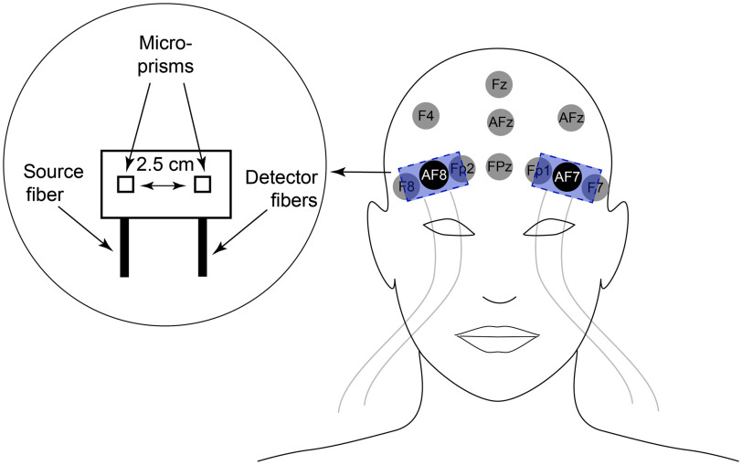
Fig. 2.
Positioning and design of optical probes. EEG recording locations in the vicinity of the probe are identified in the head image on the right. The illumination/collection from source/detector fibers was directed toward the scalp with microprisms. Source and detector prisms were separated by 2.5 cm, measured from the microprism centers. The probe was positioned on the scalp such that EEG recording locations—AF7 or AF8—were situated directly under the midpoint of the probe (equidistant from source and detector prisms).

