
Figure 2.
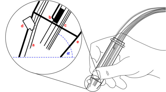
Schematic diagram of the hand-held device: (a) represents the droplet collecting tubing, (b) the LTP-emitter, (c) the DESI/EASI-emitter, (d) the camera module, (e) the housing, and (α) the probe angle. The whole setup is specified in Figures S-1 and S-2 and Table S-1 in the Supporting Information.