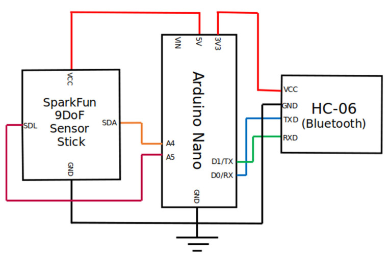
Scheme 1.
Schematic block diagram of the interconnection between the device components. The Arduino Nano board (center) acts as the control and processing unit, collecting readings from the accelerometer (SparkFun block on the left), computing the estimations of the thigh angle over time, and analyzing the resulting signal. The Arduino Nano board also makes use of the Bluetooth module (HC-06 block on the right) to exchange messages with the external mobile device over a wireless communication channel. The whole device was powered by a 9V 6LP3146 battery. While the Arduino Nano board was directly powered by the battery, the accelerometer and the Bluetooth boards were indirectly powered by connecting them to the Arduino’s 5V and 3.3V DC outputs, respectively. The battery was omitted in this scheme for the sake of clarity.

