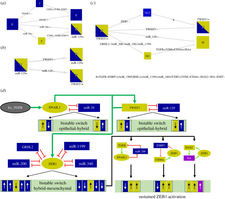
Figure 6.
Stepwise process of the model dynamics via activation of multiple circuits. HTGs are displayed as in figure 3. The simulations were performed for . (a) The initial state E (considering active SNAIL1) induces a bistability between the E and H (with the presence of miR-129) states. (b) Subsequently, the initial state H (considering active TWIST1) triggers another bistability between the H states. (c) Considering the H state with the presence of TWIST1 and additional activation of ZEB1 as the initial condition, the simulation showed another multistability between H and M states. (d) Up and down arrows represent up and downregulation, respectively. Yellow and blue colours denote E and M markers. The induction of SNAIL1/miR-34 circuit by Ex_TGFB triggers bistable switches that control the transition E to H. The activation of SNAIL1 induces the functionality of TWIST1/miR-129 circuit. The switch TWIST1 OFF/miR-129 ON stabilizes one of the H states, whereas its counterpart (TWIST1 ON/miR-129 OFF) triggers the transition to another H state which is stable due to miR-200-miR-1199-GRHL2-miR-340-ZEB1 circuits. Active TWIST1 can induce ZEB1 and subsequently inactivate miR-200, GRHL2, miR-1199 and miR-340 and inducing the transition to the M state which is sustained by TGFB/miR-200/SNAIL1, ESRP1/CD44s/ZEB1 and HAS2/HA/ZEB1 circuits.

