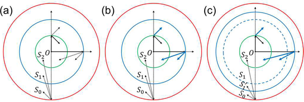
Fig. 2.
Different combinations of source locations and reconstruction locations subject to spatial aliasing in SS and IR. Three regions S0, S1, and S2 are defined in Equations (8), (16), and (22), respectively. The first line radiating from the origin O represents the range of source locations for SS, while the second line radiating from the tip of the first line represents the range of reconstruction locations for IR. A solid line means no aliasing, while a dotted line means aliasing. (a) Spatial aliasing in UBP. The innermost two-way Nyquist zone S2 is an aliasing-free region. (b) Spatial aliasing in UBP with spatial interpolation. Spatial interpolation removes spatial aliasing in three cases of IR, making the one-way Nyquist zone S1 an aliasing-free region. The dotted lines representing the three cases in (a) are changed to blue-solid lines in (b). (c) Spatial aliasing in UBP with temporal filtering and spatial interpolation. Temporal filtering extends the one-way Nyquist zone S1 in (b) to in (c), and the original S1 is marked as a blue-dashed circle for reference. Spatial interpolation further makes an aliasing-free region.

