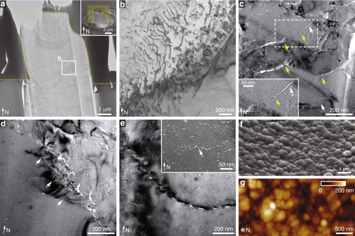
Fig. 5. Microscale deformation mechanisms in biogenic and geological calcite.
a TEM image of a thin slice taken from a significantly deformed geological calcite micro-pillar after compression testing. Inset, SEM image of the micro-pillar used for TEM sample preparation and the yellow plane shows the orientation of the TEM slice. b High magnification TEM image showing the dislocation arrays developed within the deformed geological calcite micro-pillar. c TEM image showing micro-/nano-scale cracks developed within the A. rigida biogenic calcite after deformation. White and yellow arrows indicate the cracks in the low- and high-density defect regions, respectively. d TEM image taken at the boundary of a fractured zone in biogenic calcite, showing the propagation directions of several cracks (white arrows) in parallel to the long axes of the defects, which is perpendicular to the calcite’s c-axis. e TEM image demonstrating that a crack formed via the coalescence of micro-cracks initiated from defects and followed the long-axis directions of defects. Inset: TEM imaging showing a site of crack initiation through nanoscopic damage coalescence from adjacent defects. f SEM and g atomic force micrograph (AFM) of the fractured surface of biogenic calcite, showing the nanoscale rough surfaces.

