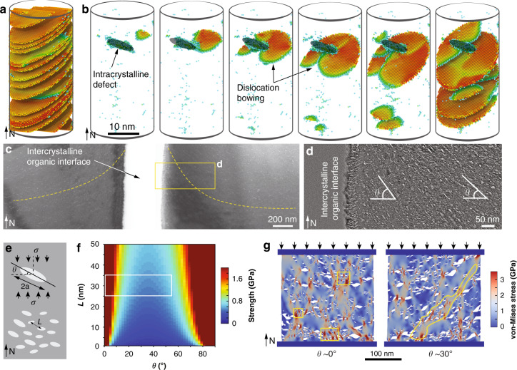
Fig. 6. Mechanical effects of intracrystalline defects in A. rigida biogenic calcite.
a, b Atomistic simulation of compression on a geological and b the biogenic calcite along the c axis, respectively. c, d TEM images showing that the orientation of the intracrystalline defects is gradually tilted towards the intercrystalline organic interfaces. The yellow dashed lines in c indicate the long-axis direction of defects locally. e Schematic model of the biogenic calcite with the presence of intercrystalline defects. f Estimated strength in relation to the spacing (L) and the inclination angle (θ) of intracrystalline defects. The boxed region highlights the actual configurations of defects observed in the A. rigida biogenic calcite. g Comparison of the stress contours and fracture patterns of biogenic calcites with defects orientations θ = ca. 0° and ca. 30° based on finite element/discrete element simulation. The boxed regions in the θ = ca. 0° model show cracks initiated at regions with a high density of defects, and the yellow region highlights an inclined damage band formed in the θ = ca. 30° model.

