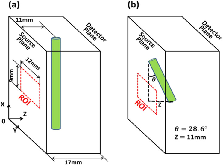
FIG. 5.
Schematics of phantom experiment geometry. (a) A plastic tube with ICG solution was placed parallel to the X axis. The tube was fixed at 11 mm from the source plane (z = 11 mm) for the study performed in Sec. IV A. The tube was moved along the Z axis for the system linearity evaluation study described in Sec. IV B. (b) The tube was tilted 28.6° with respect to the X-axis in the X-Z plane for further evaluating the system performance in Sec. IV B.

