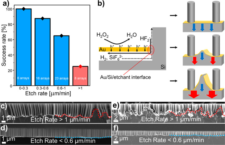
Figure 3.
Influence of the etch rate on the successful synthesis of VA-SiNW arrays via MACE, based on 53 different MACE experiments performed on substrates prepared with a similar Au film thickness but different colloidal particle deposition methods, array geometries, etchant compositions, and AZO thicknesses. (a) Percentage of successful MACE experiments as a function of etch rate. The total numbers of samples etched within an etch rate range are written in white on each bar. A successful MACE experiment refers to samples with a well-defined flat horizontal gold film after MACE, while failed samples correspond to substrates where there is a significant buckling or fracture of the gold film. (b) Schematic illustration of the film fracture origin. Left: Mass-transport limitation due to the diffusion of HF2–, H2, and SiF62– under the gold film. Right: The blue arrows represent low-etch rate regions, while the red arrows represent regions where the etch rate is higher. Top: No mass-transport limitation (low hole injection and etch rate); Center: Some mass-transport limitation leads to a larger etch rate at the Au/Si/etchant interface and buckling of the gold film (moderate hole injection and etch rate); and Bottom: Significant mass-transport limitation leads to spatially inhomogeneous etch rates and gold film fracture (high hole injection and etch rate). (c–f) Secondary electron cross-sectional SEM images of typical arrays synthesized with high etch rates (i.e., >1 μm/min), leading to the buckling and in some cases, fracture of the gold film (c,e), and at low etch rates (i.e. <0.6 μm/min), yielding homogeneous etching, indicated by a flat gold film (d,f). (c,d) Pitch: = 590 nm. (e,f) Pitch: 1100 nm.

