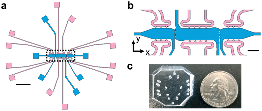
Fig. 1.

Schematic of microtissue platform for biomechanical investigations. (a) A schematic of the full microtissue device showing three tissue chambers (blue) and media lines (pink) for each chamber. Each tissue chamber can be loaded independently of adjacent chambers; the individual media lines for each tissue chamber allows for control over interstitial flow directionality and magnitude between microtissues. Scale bar = 2 mm. (b) Inset from A (black dotted lines) to show communication ports (20 μm) between microtissues. Ports are sized to allow for mechanical crosstalk between microtissues. Scale bar = 500 μm. (c) Photograph of PDMS microtissue platform with holes punched for cell/gel loading and feeding ports.
