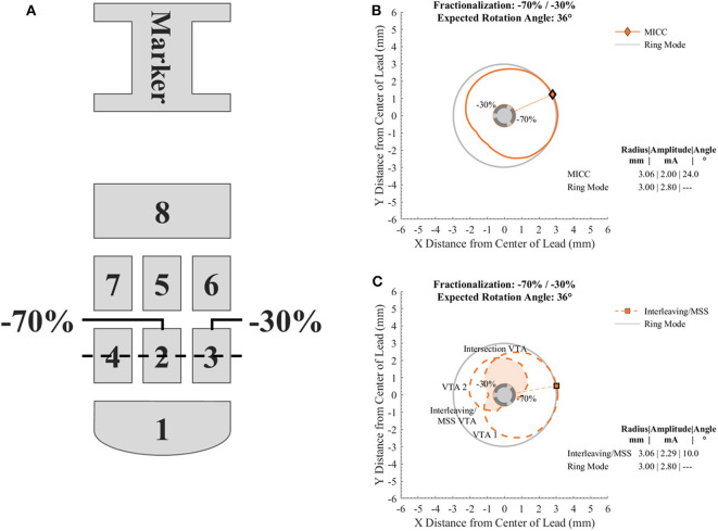
Figure 1.
Diagram of the electrode array of the directional lead used to generate the VTAs and cross sections of VTAs generated with a target radius of 3.00 mm and a fractionalization of −70%/−30%. (A) Electrode nomenclature relative to the orientation marker on the top of the lead. For the case shown, electrodes 2 and 3 were used for the generation of the VTAs with a pulse amplitude distribution of −70 and −30%, respectively. The dotted line across electrodes 2, 3, and 4 indicates the level at which cross sections of VTAs were analyzed. (B) Cross section of a VTA generated for MICC. (C) Cross section of VTAs generated for Interleaving/MSS. VTA 1 and VTA 2 are VTAs generated for each of the activated electrodes. The union and intersection of VTA 1 and VTA 2 create the Interleaving/MSS VTA and Intersection VTA, respectively. The Intersection VTA is exposed to a higher stimulation frequency than the rest of the Interleaving/MSS VTA. Markers and radial lines indicate the radii and rotation angles of the VTAs.

