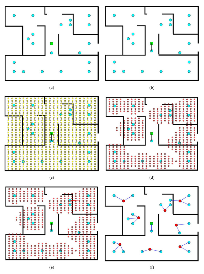
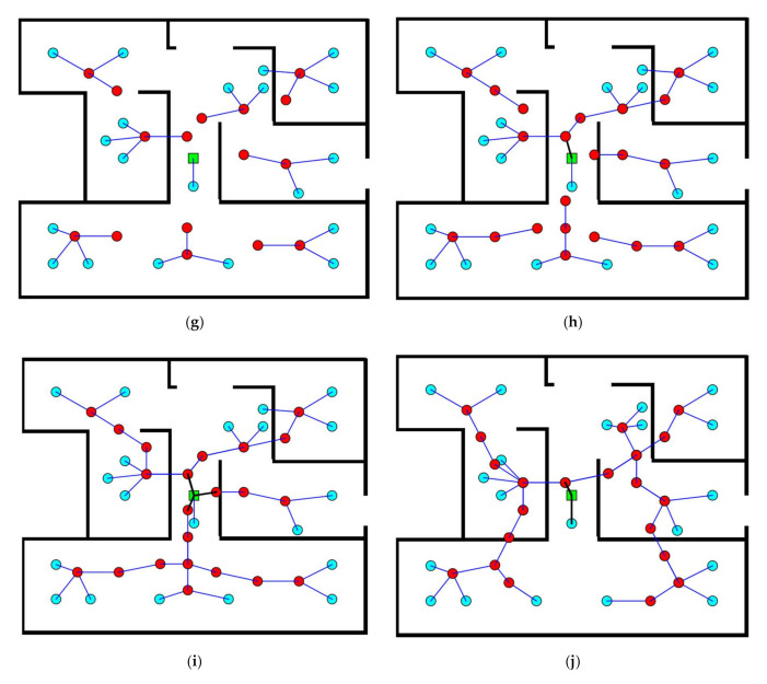
Figure 2.
Illustrative example: (a) Initial layout; (b) Connection of an end device (ED) to the base station (BS); (c) grid construction over the entire floor plan; (d) routers list filtering; (e) best router proposal for a given ED; (f) connection of all EDs to routers; (g) connection of the first set of routers to a second set; (h) connection of the second set of routers to a third set; (i) final design; and (j) an alternative final design.


