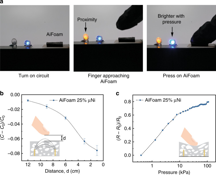
Fig. 6. Capacitive proximity sensing and resistive pressure sensing.
a Photographs showing both proximity sensing and pressure sensing of AiFoam sensor. Left The blue LED is activated, indicating the electrical circuit is turned on. Middle The orange LED lighted up when the human finger approaches to the sensor. Right The blue LED becomes brighter when the finger touches and presses the sensor. b The capacitance change responses on the distance between the finger and the AiFoam sensor (with 25 vol% μNi). The error bars are calculated based on three tests. C0 represents the initial capacitance of the sensor and C represents the capacitance of the sensor during the proximity test. d represents the distance between the human finger and AiFoam. c The resistance change responses on external pressure of AiFoam sensor (with 25 vol% μNi). R0 represents the initial resistance of the sensor and R represents the resistance of the sensor during the pressure test.

