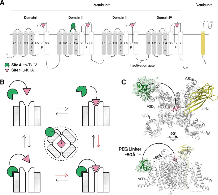
Figure 1.
NaV channel architecture and overview of the bivalent inhibitor strategy. (A) Topology of NaV channel α- and β-subunits. The α-subunit comprises four domains (denoted I–IV), with each domain containing six transmembrane segments (S1–S6). Segments S1–S4 in each domain form a voltage-sensing domain (VSD, gray), while S5, S6, and the membrane-penetrant pore loops (P-loops) form the pore domain (white).1,4 (B) Schematic of the bivalent ligand strategy. Initial binding of either a gating modifier peptide (green) or a pore-blocking peptide (magenta) should bring the other peptide close to the channel, thereby enhancing binding kinetics (red arrows) and potency compared to those of monovalent ligands. The dotted line illustrates the spatial limit of the local concentration effect of the conjugated gating modifier when the pore blocker is bound. (C) Cryo-electron microscopy structure of hNaV1.7-β1 in the presence of HwTx-IV and μ-KIIIA. The hNaV1.7-β1 structure was used to determine the distance between the two peptides as this channel is our target of interest and because this structure contains HwTx-IV. A triple-mutant variant of HwTx-IV (E1G, E4G, Y33W; m3-HwTx-IV) was placed in the HwTx-IV density in a random orientation due to the unknown interaction sites with the channel. The distance between the center of the m3-HwTx-IV density and the N-terminus of μ-KIIIA is ∼50 Å in a direct line (dotted line) (i.e., if steric overlap is ignored) and ∼80 Å considering the length of a half-circle (solid line) that comfortably avoids steric overlap with the channel (PDB entries 5T3M, 6J8E, and 6J8G and EMD entry 9781).18,27 Figures were generated using UCSF Chimera, version 1.13.1.

