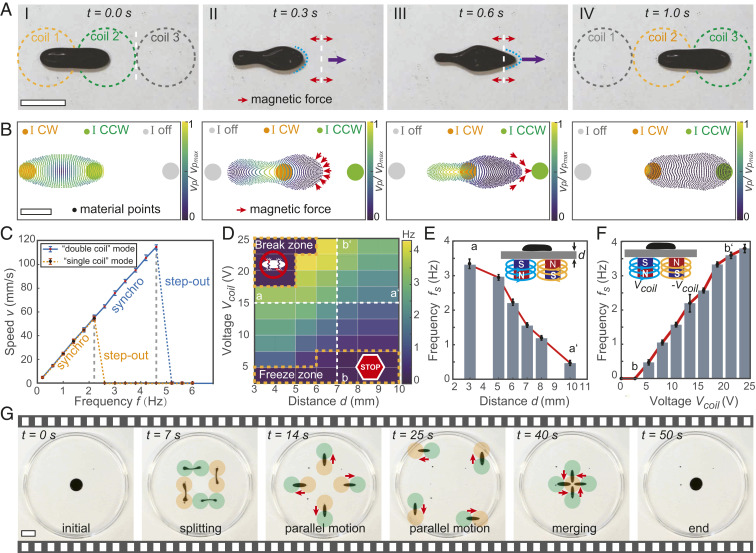
Fig. 3.
Actuation mechanism and characterization of the single-body and coordinated motions of FDRs. (A) Snapshots of the dynamic motion of an FDR actuated in the double-coil mode. The white dashed lines indicate the boundary line of neighboring coils. The red arrows near the white dashed lines indicate the magnetic pulling forces change their directions. The purple arrows and blue dots mark the motion and shape of the FDR, respectively. (Scale bar, 20 mm.) (B) Simulated velocity of an FDR under the spatiotemporal magnetic pulling forces. The applied current in each coil is marked as clockwise (CW), counterclockwise (CCW), or “off.” (Scale bar, 10 mm.) (C) Speed of an FDR as a function of the actuation frequency in the double-coil (blue lines) and single-coil (yellow lines) modes. Error bars represent the SD for measurements. (D) The step-out frequency of an FDR in the double-coil mode as a function of the applied voltages in the electromagnet array (equivalent to and the actuation distance from the electromagnet array to the actuation plane in water. In the “freeze zone,” FDRs cannot move. In the “break zone,” FDRs split. (E) The step-out frequency for an FDR as a function of along the line aa′ in D. (F) The step-out frequency for an FDR as a function of the applied voltage along the line bb′ in D. (G) Sequential snapshots of the splitting, coordinated navigation, and merging behaviors of FDRs. Red arrows indicate the moving directions of FDRs. The yellow and green dots denote coils with currents in the CW and CCW directions, respectively. (Scale bar, 20 mm.) In all experiments, only the ferrofluids with a dynamic viscosity of 8 mPa·s (EMG 901; Ferrotec Corporation) were used.

