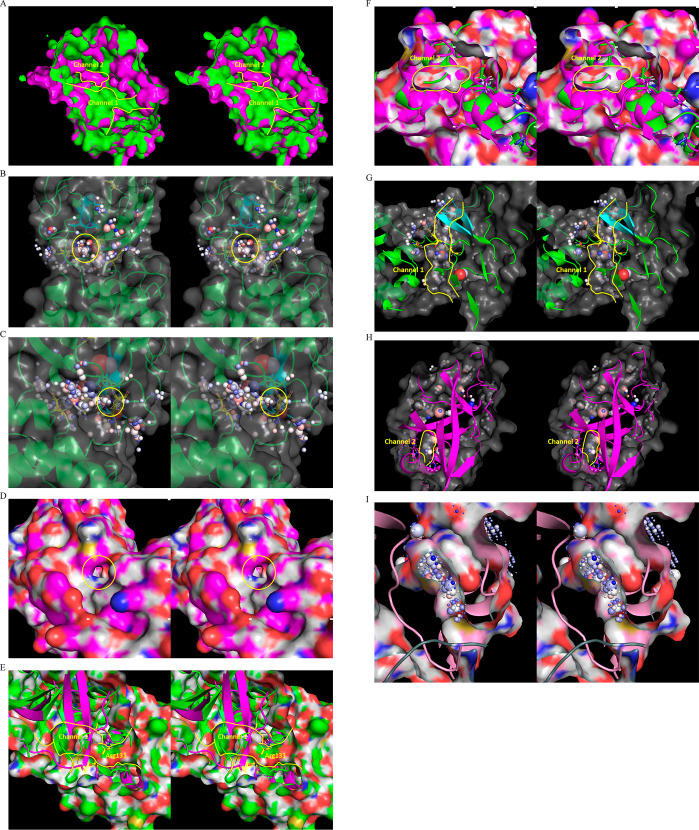
Figure 15.
(A) Stereo view of buried water channels 1 and 2 (yellow outline) within the domain {1–2}–3 interface in the M2pro (green) and M2 (magenta) states, captured respectively in 2QCY and 2Q6G. (B) Stereo view of entrance 1 of channel 1, showing the water-occupied voxels within the peri-entrance region. The sphere radii are scaled according to occupancy, and color-coded according to the preference of each voxel for water H or O (see the “Materials and Methods” section). (C) Same as B, except for entrance 2. (D) Stereo view of the channel 2 entrance, which is closed in the substrate/inhibitor-bound state. (E) Stereo view of channel 1 in the M1pro state (2QCY) (green) overlaid on domain 3 in the M2 state (2Q6G) (magenta), showing complete disruption of the channel by two β-strands of domain 2, together with Arg131 (yellow). (F) Stereo view of channel 2 in the M2pro state (2Q6G) (magenta) overlaid on domain 3 in the M1 state (2QCY) (green), showing complete disruption of the channel by Arg4, Lys5, and Met6 of the NTL backbone. (G) Stereo view of the occupied voxels in channel 1 (outlined in yellow). The corresponding water is expelled via rearrangement of the domain {1–2}–3 interface upon entry to the M2pro state. (H) Stereo view of the occupied voxels in channel 2 in the M2 state. (I) Water trapped within channel 2 is vented subsequent to product dissociation, as captured in the apo dimeric structure (6M03).

