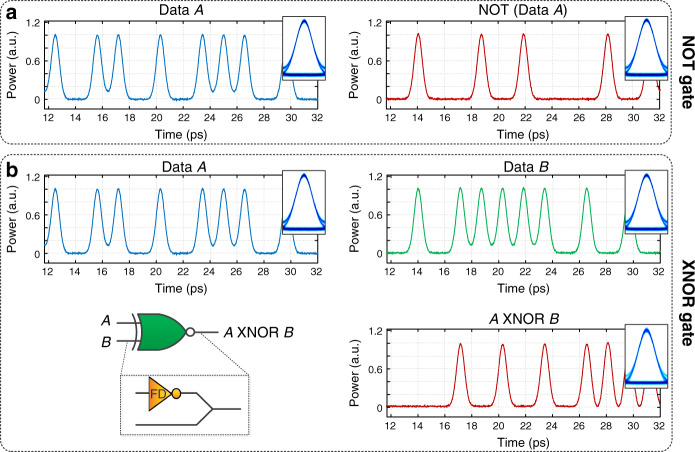
Fig. 3. Demonstration of frequency-domain, passive logic NOT and XNOR gate through numerical simulation.
a Left: 13 bits at 640 Gbit/s of a 128 random bit sequence (RBS) input to NOT gate, Right: NOT gate output of same 13 bits, insets: eye diagrams. b Top: 13 bits at 640 Gbit/s of two 128 random bit sequence inputs to the XNOR (Data A and Data B), Bottom right: corresponding XNOR output of 13 bits from logical operation of Data A and Data B, insets: eye diagrams.

