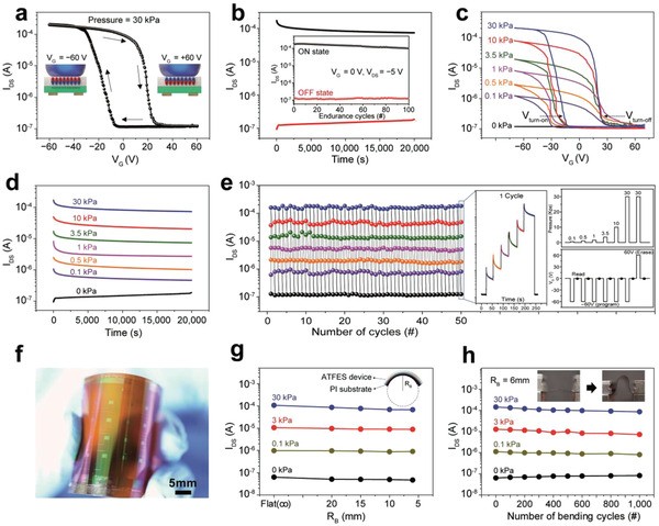
Figure 2.

Switching and mechanical characterization of the ATFES. a) I DS –V G transfer curve showing current hysteresis stemmed from nonvolatile ferroelectric polarization of the P(VDF‐TrFE) layer. Pressure = 30 kPa. b) The retention characteristic of ON and OFF states at V G = 0 V and V DS = −5 V. Inset: program/erase endurance up to 100 cycles. c) I DS –V G transfer curves at seven different pressures ranged from 0 to 30 kPa, and d) the retention of each state at V G = 0 V and V DS = −5 V. The programming pressures and voltage (V G = −60 V) were applied for 1 s. e) Repetitive multiple program/erase switching endurance test with seven different pressures. The inset shows a real‐time response, pressures sequence, and gate voltages sequence, respectively, for one cycle. After programmed or erased, I DS was read at V G = 0 V and V DS = −5 V. f) Photograph of a flexible ATFES array on the PI substrate, g) four distinct levels at V G = 0 programmed by V G = −60 V as a function of R B, and h) bending endurance for the cycle test up to 1000 cycles under R B = 6 mm. The inset photograph shows a flexible ATFES array in bent and unbent states.
