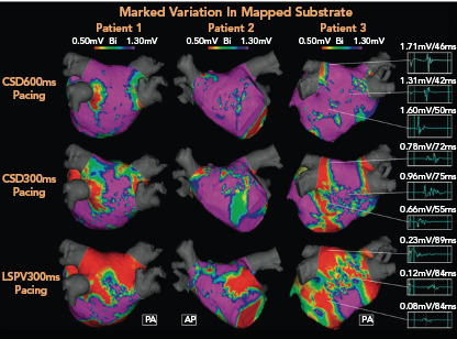
Figure 3: Rate- and Direction-dependent Variation in Mapped Substrate.

Electroanatomic maps demonstrating significant progressive increase in low-voltage areas (LVAs; <0.5 mV) typically targeted in adjective scar homogenisation ablation strategies according to different pacing methods in three different patients (area in red). Complex fractionated electrograms from corresponding regions in patient 3 (right side, a 72-year-old man with early persistent AF) are longer, with lower voltages in response to each subsequent pacing strategy. Impact of pacing cycle length and wavefront direction in the potential atrial area included in substrate ablation is highlight. AP= anteroposterior; CSD = distal coronary sinus; LSPV = left superior pulmonary vein; PA = posteroanterior. Source: Wong et al. 2019.[55] Reproduced with permission from Elsevier.
