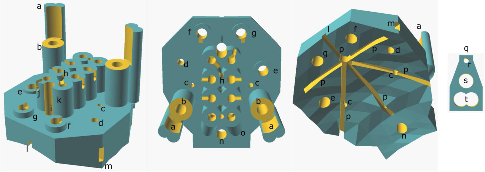
Figure 1. Headplate CAD Model.

(Left) Diagonal view from above and anterior to the headplate, (middle) from above and (right) from below, showing the skull-conformal polygon base. (a) Microdrive guide post, (b) microdrive screw housing, (c) microwire hole, (d) cannula hole, (e) parietal screw electrode hole, (f) frontal screw hole, (g) ground screw hole, (h) reference wire tunnel entrance, (i) Bregma siting hole, (j) example of wire notch, (k) Mill-Max connector receptacle, (l) anterior glue furrow, (m) lateral glue furrow exit, (n) reference screw hole, (o) EMG wire tunnel outer housing, (p) glue furrows, (q) microdrive platform, (r) microwire hole, (s) microdrive screw hole and (t) the hole for the microdrive guide post.
