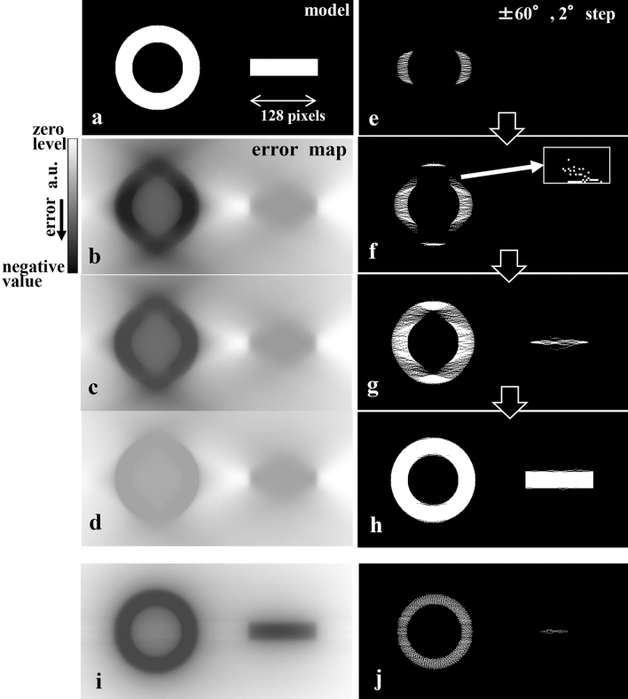
Figure 3.
Examination with a simple binary model using the basic reconstruction procedure. (a) Model susceptible to the missing wedge. (b–d) Changes in the error maps from the initial stage (b), halfway (c), and final reconstruction (d) for a test condition of ± 60° with 2° steps. Error maps are affected by the missing wedge due to the calculation with a simple back projection under the limited angular range condition. (e–h) Process of the present reconstruction using QUs (small white dots shown in the enlarged image inserted in (f)) from the initial stage (e) via (f) and (g) to the final reconstruction (h). QUs are arranged one-by-one in the negative maximum error position in the current error map, which is updated after each QU placement. In the initial stage, QUs are not arranged in the affected parts of the error map because the error amount in these parts is relatively small compared to those in the structural parts as shown in (e). Later, QUs are not arranged in the affected parts because the error amount in both parts gradually becomes smaller. Eventually a finite number of QUs are placed, and the missing wedge artefact in the cross-section image is avoided. (i and j) Error map in a near initial stage and the corresponding halfway QU arrangement for the almost ideal condition (tilt-angle range ± 90° with 2° steps). Although the error map is no longer distorted, QUs are not uniformly arranged because the error amount differs among structural parts.

