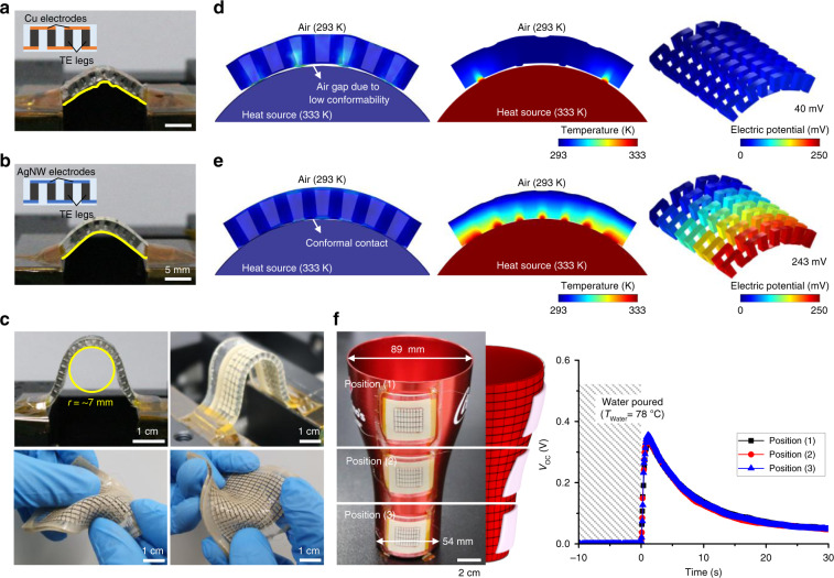
Fig. 5. Mechanical conformability of the compliant TEG.
a, b Photographs of bent TEGs comprising Bi2Te3 legs and Cu electrodes (a) and AgNW-based soft electrodes (b). The each inset shows schematic illustration of side view of each TEG, respectively. Scale bars, 5 mm. c Photographs of the compliant TEGs showing excellent conformability under various deformations. Scale bars, 1 cm. d, e FEA results showing different deformation and heat transfer behaviors corresponding to TE performance for the TEG with Cu electrodes (d) and AgNW-based soft electrodes (e). f Photographs of a TEG attached to different positions (top, middle, and bottom side) of a bell-shaped aluminum cup. The TEG established conformal contact with the three-dimensional (3D) surface of the aluminum cup. The middle schematic image shows the anisotropic bending curvatures of each position at which the TEG was attached. The right graph shows the time-resolved VOC of the TEG attached to the three positions when hot water is poured into the aluminum cup. Scale bar, 2 cm.

