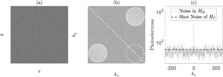
Fig. 3.
(a) Camera plane hologram, , formed using DC subtraction temporal filtering. (b) Arbitrary logarithmic representation of a reconstructed intensity hologram, . The two heterodyne gain terms, , are masked by the dotted circles (which are a conjugate pair), the shot noise mask, , is depicted by the dashed circle. (c) The thin grey solid line shows the value of the diagonal white dashed line that has been superimposed on , averaged over pixels in . The thick dashed black line shows the average shot noise value of all the pixels in for this particular image reconstruction.

