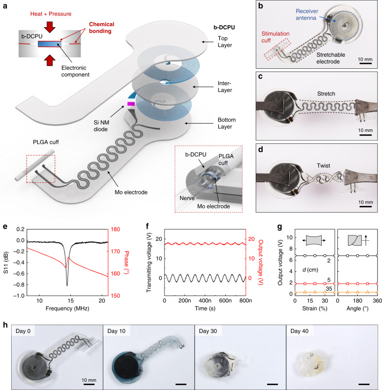
Fig. 1. Designs and properties of a long-lived, stretchable, and wireless bioresorbable electrical stimulator to enhance recovery from peripheral nerve injuries.
a Schematic illustration of the device design. The electronic component consists of three functional parts: (i) a wireless receiver that acts as a radiofrequency power harvester and control interface, built with an inductive coil (Mo, 50 μm thick), a radiofrequency diode (Si NM active layer, 1.2 μm thick), and an interlayer (bioresorbable dynamic covalent polyurethane (b-DCPU), 50 μm thick); (ii) stretchable extension electrodes with serpentine structures (Mo, 15 μm thick with a 200 μm width); and (iii) a stimulation cuff (poly(lactic-co-glycolic acid) (PLGA), 30 μm thick) with exposed electrodes at the ends as an interface to the nerve. All parts of the system, excluding the stimulation cuff, are sandwiched between two layers of bioresorbable elastomers (b-DCPU, 100 μm). The schematic illustrations in the inset show the thermal and stress-activated bonding process for b-DCPU (top, left) and the contact between the nerve and the stimulation cuff (bottom, right). b Optical Image of a completed device. c, d Photographic images of stretched (30%) and twisted (360°) devices. e Radiofrequency behavior of the stimulator (black, S11; red, phase). The resonance frequency of ~16.0 MHz allows magnetic coupling in a frequency regime with little parasitic absorption by biological tissues. n = 3 independent samples. f Example output waveform (stimulator, red) wirelessly generated by an alternating current (sine wave) applied to the transmission coil (transmitter, black). n = 3 independent samples. g Output voltage of a device as a function of tensile strain (left) and twist angle (right) at different distances between the harvester and transmitter (black, 2 cm; red 5 cm; orange, 35 cm). n = 3 independent samples. h Images of accelerated dissolution of a bioresorbable wireless stimulator associated with immersion in PBS (pH = 7.4) at 90 °C.

