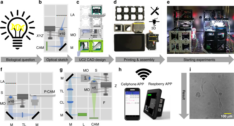
Fig. 2. Rapid Prototyping using UC2.
Common workflow to build a UC2 application: (a) Starting with a biological question/idea in need of an imaging device drafted in (b) (inverted incubator microscope) and transferred using UC2 components from the CAD library in (c). After printing and assembling it (d) the device will be placed in its working environment (e.g. incubator) (e) ready to acquire long-term image series of e.g. MDCK cells visualized in (i) and Supplementary Video 6. Remote-control is granted using “smart components” (e.g. cellphone, Raspberry Pi) in (h). Reusing components allows the conversion into a cellphone-microscope (f) or light sheet microscope (g) within minutes (see Supplementary Video 5) and Supplementary Notes 7.8). CL: cylindrical lens, TL: tube lens, L: Laser, LA: LED-array, M: Mirror, MO: Microscope Objective, P-CAM: Detector (smartphone or Raspberry Pi), S: sample positioning stage, F: emission filter, Z: focusing stage.

