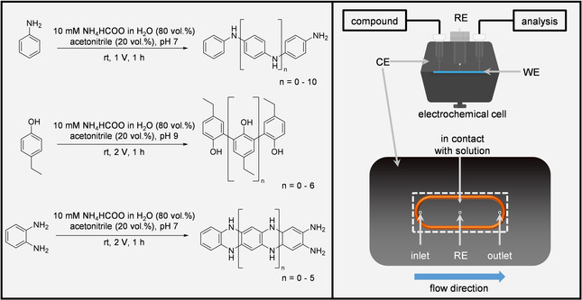
Scheme 2.

Left: Polymerized organic compounds and respective electrochemical conversion parameters. Each compound was dissolved in the respective solvent mixture resulting in a total concentration of 10 mm. The presented structures are examples from a large variety of different possible isomers of the observed products. Right: Overview of the electrochemical three‐electrode setup. The lower part of the Scheme shows the CE of the EC cell. The orange O‐ring encloses the region, where the CE and the WE are in contact with the respective compound solution. The three circles represent three different channels belonging to the inlet, the outlet and the connection to the RE. The dashed rectangle represents the area covered by the BDD WE (12×30 mm).
