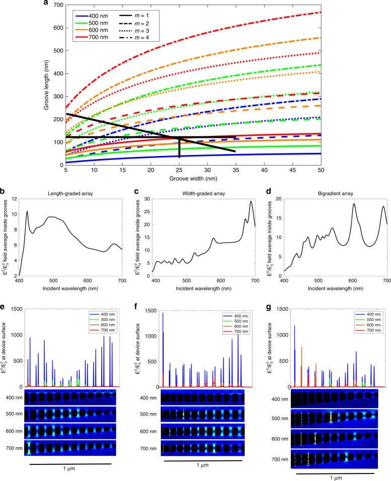
Fig. 3. Design of three array configurations and resulting electromagnetic field profiles.
a Analytical calculation of the first four resonant modes of an Ag-MgF2-Ag cavity in the visible regime. Black lines illustrate the groove geometries used in the three array designs. The vertical line represents the length-graded array, the horizontal line represents the width-graded array and the diagonal line represents the bigradient array. b–d COMSOL simulation of the average field intensity inside the grooves across the entire visible spectrum for the length-graded, width-graded and bigradient designs, respectively. e–g COMSOL simulation of the electric field intensity at the surface of the array for the length-graded, width-graded and bigradient designs, respectively, at select wavelengths in the visible regime, along with simulated two-dimensional field intensity maps at the four wavelengths

