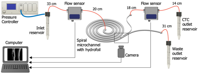
Figure 4.
Test setup. A pressure-driven flow was generated inside the microfluidic chip using a pressure controller connected to pressurized N2. Two flow sensors were used for continuous measurement of the flow rate at the inlet and waste outlet of the chip. A custom-designed microfluidic chip holder houses the microfluidic chip and facilitates fluidic connections to the microchannel. An inverted fluorescent microscopy equipped with a highspeed camera connected to a computer were used for optical observation. Fused silica tubing was used to make fluidic connections (red lines).

