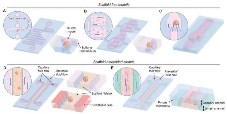
Figure 7.
Schematic representation different microfluidic devices used. (A) A device containing a sinuous microchannel each of which contains five microwells for sedimentation trapping of the loaded microtissues or spheroids [127]. (B) A device containing permanent U-shaped microstructures. The flow of culture medium towards the microstructure pushes the cells inside [125]. (C) A two-layer microfluidic chip. The spheroid is immobilized in the higher part of the channel before the dam, where the height decreases from 250 to 25 µm [129]. (D) These devices consist of 2 media channels engulfing an extended, central region containing the scaffold/matrix. The devices contain an array of trapezoidal posts that cage the matrix solution into well-defined regions with uniform surface interface. The side channels can be perfused with endothelial cells to simulate the endothelial wall [130,132]. (E) Microfluidic platform with three types of channels - capillary, interstitial and lymphatic channels (noted with red, yellow and red colors). These channels are independently pressurized to mimic the elevated interstitial fluid pressure and are configured in a 3D structure by stacking two polydimethylsiloxane (PDMS) layers of microchannels with a porous membrane sandwiched between the layers [123].

