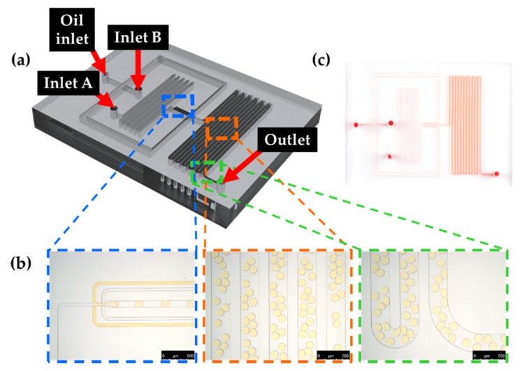
Figure 5.
Droplet generation using the microfluidic device. (a) Schematic diagram of the microfluidic device for droplet generation. (b) Microscopic images of flow-focusing structure (blue box) for droplet generation, incubation channels (orange box) and outlet (green–box) (scale bar = 500 μm). (c) A photographic image of the fabricated PDMS microfluidic device. The microfluidic channel was visualized with red food coloring.

