
Fig. 1.
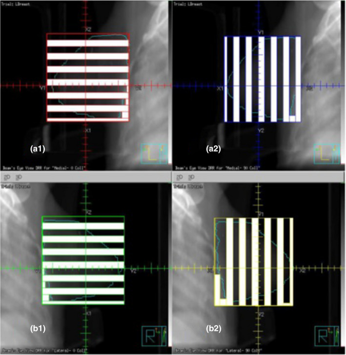
Schematic diagram of multi‐leaf collimators (MLCs) used in forming a GRID field in this study. Upper two figures (a1 and a2) show two orthogonal fence fields used to form one side of tangential GRID field. Lower two orthogonal fence fields (b1 and b2) were used for another side of the tangent GRID field.