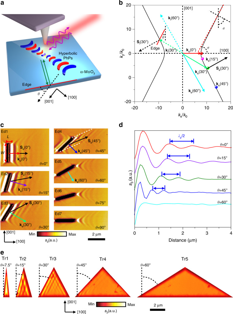
Fig. 1. Edge-tailored hyperbolic PhPs in α-MoO3.
a Schematic diagram of edge-tailored PhPs in α-MoO3. The edge orientation is defined as angle θ with respect to the [001] direction. Green arrows indicate the incident PhPs waves launched by the laser-illuminated (purple curve arrows) AFM tip and reflected by the edge (red line). b Angle-dependent ke isofrequency contour of PhPs in α-MoO3 at ω = 889.8 cm−1. The solid lines and points stand for experimental results concluded from Fig. 1c. The green and black dotted arrows illustrate the incidence wavevector ki and Poynting vector Si, respectively. Generally, ki and Si are non-collinear. The reflected Poynting vector Se (solid arrows) is not parallel to the reflected wavevector ke (different color solid arrows) but antiparallel to Si. σ is the open angle. c Real-space imaging of edge-tailoring PhPs at angle-dependent α-MoO3 edges (length L: 2.5 µm; width W: 200 nm; sample thickness d: 210 nm, L and W defined in the Ed1). d s-SNOM line traces along the direction perpendicular to the edges in Ed1-Ed5. e Near-field amplitude s(ω) of PhPs on isosceles triangle α-MoO3 nanocavities with bottom edge perpendicular to the [001] crystal direction (height length: 4.33 μm; thickness: d = 175 nm); The angles between adjacent sides of the series of triangles with respect to the [001] direction are approximately 7.5°, 15°, 30°, 45°, and 60°, respectively.

