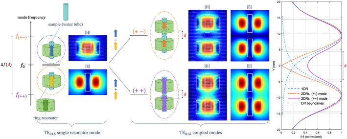
FIGURE 1.

Hybridization scheme and mode field profiles of the first transverse electric (TE) mode of two coupled dielectric resonators. The electromagnetic coupling of the individual TE01δ modes of the single DRs, initially at the same frequency f0 gives rise to two coupled modes whose frequencies are shifted lower and higher than f0.The lower‐frequency, symmetric mode is denoted (++) and is equivalent to a magnetic dipole longer than the initial TE01δmode with zero coupling. The higher‐frequency, antisymmetric mode, denoted (+‐), corresponds to two magnetic dipoles aligned in opposite directions such that the electromagnetic (EM) field maps represent the H‐ and E‐fields of the single resonator TE01δ mode and of the coupled modes. The maps were obtained with the Eigenmode Solver of CST Studio, normalized w.r.t. the maximum in each case and plotted on a linear scale from 0 to 1. The graph on the right represents the H‐field magnitude profiles along the resonator axis for the (++) (purple line) and (+‐) (orange dotted line) modes. For comparison, the H‐field amplitude of the original TE01δ mode has been displayed for each single resonator (blue dashed line)
