
Figure 1.
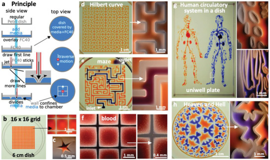
Principle. a) A “microjet” of an immiscible fluorocarbon (FC40) is projected through FC40 and media on to the bottom of a dish; media is pushed aside, and FC40 sticks to the bottom (it wets polystyrene better than media). Moving the jet now draws lines to form a grid with FC40 walls. b) A 16 × 16 grid (interchamber spacing 1.9 mm; 600 nL red dye added to each chamber; zoom shows fluid walls). c) Star‐shaped walls (red dye added after jetting). d) A square with one internal wall shaped like a Hilbert curve (a continuous line with many 90° and 45° turns). Red dye was added at many points; it diffused around the wall throughout the square. Zoom shows some turns. e) Path through a maze with a single inlet and outlet. The circuit was built by jetting FC40 through media plus red dye; when blue dye is pumped into the inlet, it takes the path of least resistance through the maze. Zoom shows some walls. f) Part of 16 × 16 grid where FC40 is jetted through blood instead of media. Zoom shows the jet leaves no cells in what are now FC40 walls. g) Human circulatory system in a uniwell plate with dimensions of a 96‐well plate. Red and blue dyes were infused into major “arteries” and “veins” which then flow/diffuse throughout each system. Zooms show regions in white rectangles. h) Walls were built in design inspired by “Circle Limit IV (Heaven and Hell)” by M.C. Escher – WikiArt. Patterns for Figure 1d,e,g were obtained from the following sources: © Wikimedia Commons (author Braindrain0000), Can Stock Photo Inc. (author Taui), pngegg.com, respectively. Images used to inspire Figure 1d and 1e were obtained and used with permission from Wikimedia Commons (name "Hilbert curve.png", author Zbigniew Fiedorowicz) and Can Stock Photo Inc. (image number csp49511651, author Taui)”. Image used to inspire Figure 1g is a public domain image. Image used to inspire Figure 1h was from Sazdanovic et al. [ 16 ] and is used under the terms of the CC‐BY license, Copyright 2012, Radmila Sazdanovic, published by MDPI.