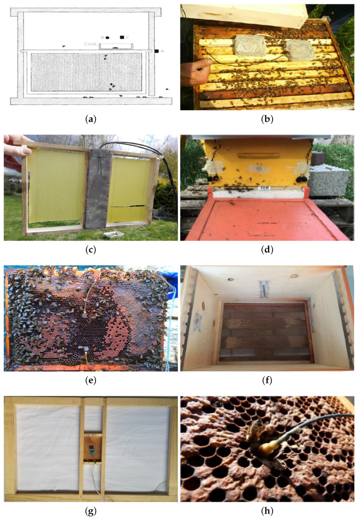
Figure 2.
Different microphones and accelerometers placement inside the colonies, based on different approaches. In particular: in (a) from [27], B is the microphone used and it is placed above the queen cage. (b) shows the microphone placement of [63]: the sensors are placed upon the brood frames inside a cage to protect them from propolization. (c) shows the solution adopted in [45], where a custom frame with the sensors inside has been chosen. (d) refers to the approach proposed in [44], with microphones placed outside the hive, so that a cage to protect against propolization is not necessary. In (e), accelerometers placement proposed in [43] is presented: the sensors exploit vibrations and do not suffer from propolization problems. (f) belongs to approaches presented in [51,52,57,58]: the microphones are hidden inside the hive walls, and a grid is used to protect them. (g) from [54] shows a custom brood frame. Finally, (h) from [61] shows accelerometers positioning similar to the one proposed in [43].

