
Figure 2.
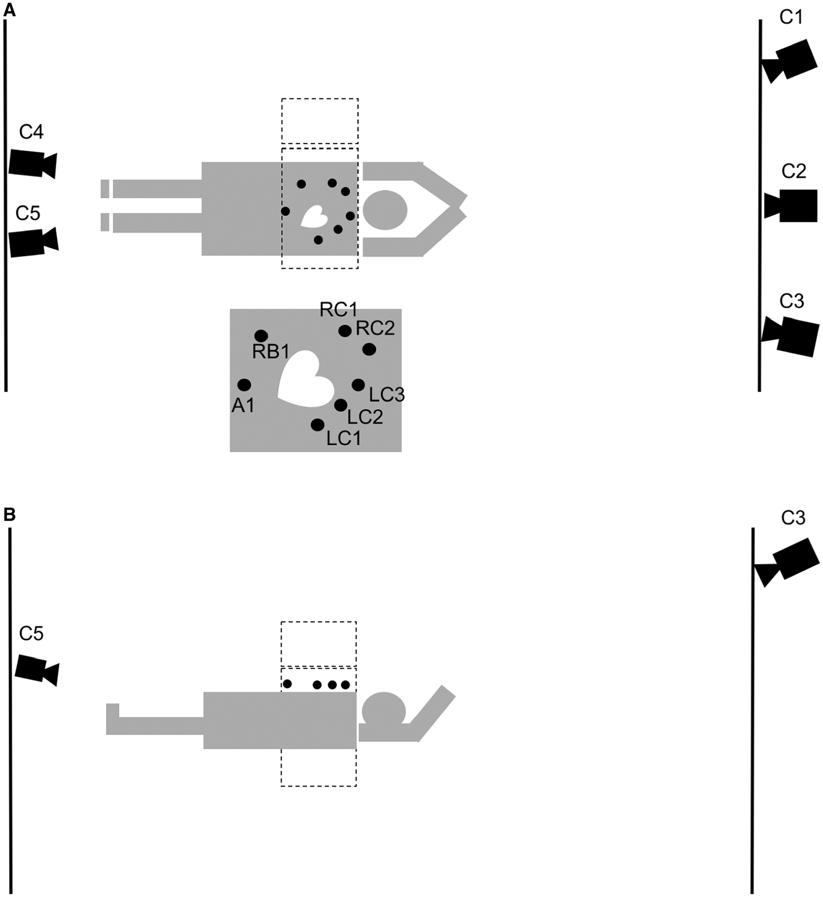
A diagram of the visual tracking setup from two different aspects, above (A), and left side (B) of the patient. Three Vicon cameras are placed at the head end of the patient behind the control room lead glass window (C1–C3), while two are placed at the foot end of the patient. (C4, C5). The two gamma camera heads (dotted lines) are at 90 and 180 degrees with the markers place on the right chest (RC1, RC2), the left chest (LC1-LC3), the right rib (RB1), and the abdomen (A1). The makers visible in (B) are LC1-LC3, and A1. The diagram is not strictly drawn according to scale.