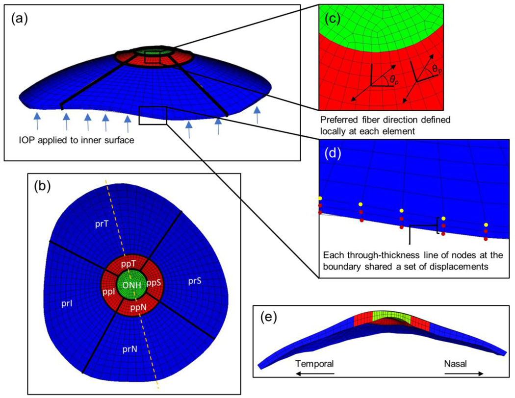
Fig. 4.
FEM details. a Side view of a finite element model mesh. IOP was applied to the anterior surface as indicated by the blue arrows. b Top view of the meshed model with regions labelled. Orientation is the same as in the top view from Fig. 3. Dashed line indicates cross-sectional cut shown in (e). c Zoomed in view of the mesh in the peripapillary and ONH regions. The preferred fiber direction was defined locally at each element. d Zoomed in view of the model outer edges (furthest from the ONH). Displacements from the DIC facet map were interpolated and applied as boundary conditions to nodes on the posterior boundary edge (yellow dots). Each through-thickness line of nodes (red dots) on the boundary surface shared displacements with the closest posterior boundary edge node, i.e. with the nearest yellow dot. e Temporal-Nasal cross-sectional view of the model. Abbreviations: optic nerve head (ONH); peripapillary superior, temporal, inferior, and nasal regions (ppS, ppT, ppI, ppN); and peripheral superior, temporal, inferior, and nasal regions (prS, prT, prI, prN)

