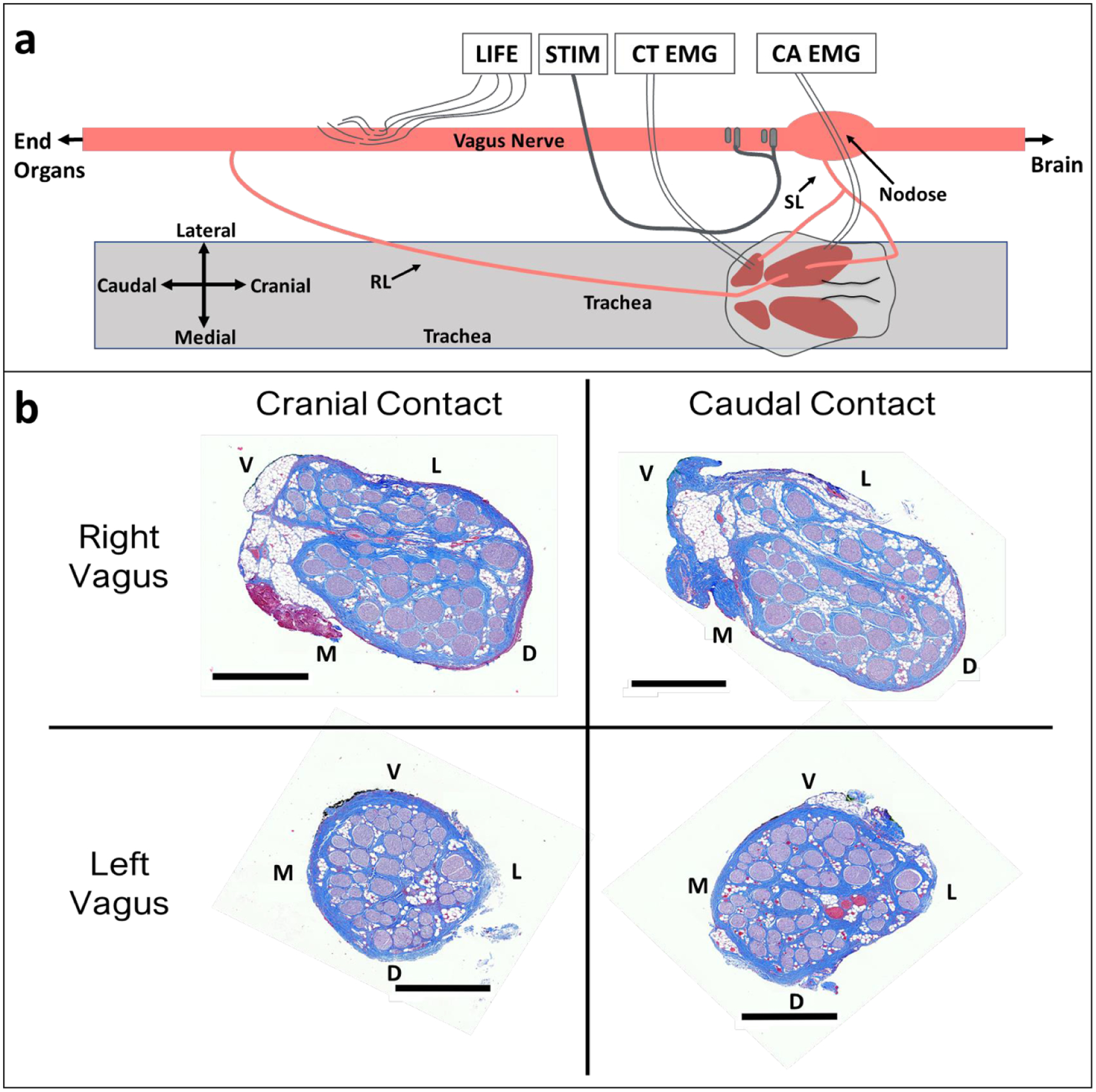
Figure 1.

Vagus nerve anatomy and experimental setup. (a) Diagram (not to scale) of surgical window showing key anatomy and relative electrode locations. Longitudinal intrafascicular electrode (LIFE), bipolar helical clinical stimulation lead (STIM), cricothyroid muscle (CT), cricoarytenoid muscle (CA), electromyography (EMG), superior laryngeal (SL), recurrent laryngeal (RL). (b) Representative cross sections from left and right vagus nerves obtained from the location along the vagus nerve where stimulation electrode contacts were placed. Black scale bars are 1 mm. Letters indicate anatomical directions ventral (V), lateral (L), medial (M), and dorsal (D).
