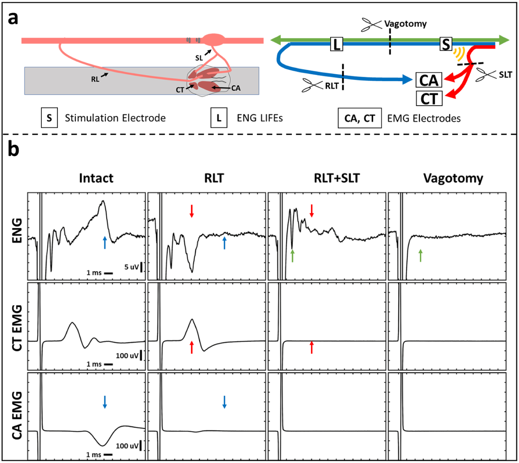
Figure 4.

ENG and EMG recordings before and after transections. Transection of recurrent laryngeal branch (RLT) and superior laryngeal branch (SLT) eliminated long- and short-latency EMGs, respectively. Transection of the vagus trunk eliminated all ENGs. (a) Diagram of the transection methods. Left panel shows a diagram of the surgical window. Right panel shows a wiring diagram of nerve fibers with transection locations (scissors). Blue line depicts recurrent laryngeal branch fibers, red line depicts superior laryngeal branch fibers, and green line depicts other vagus nerve fibers. Yellow semi-circles indicate expected current leakage out of the nerve cuff insulation acting on the superior laryngeal branch fibers that lie outside the cuff. (b) One channel of ENG (top row) and two channels of EMG (cricothyroid (CT; middle row) and cricoarytenoid (CA; bottom row)) collected simultaneously. Columns represent different time points in order from left to right with an additional transection at each step starting from no transections (intact, first column). Stimulation parameters for every column are charge-balanced symmetrical biphasic pulses at 3 mA with 200 μs per phase, delivered at 30 Hz for 30 s. Paired colored arrows highlight components of the signal that changed before and after each transection.
