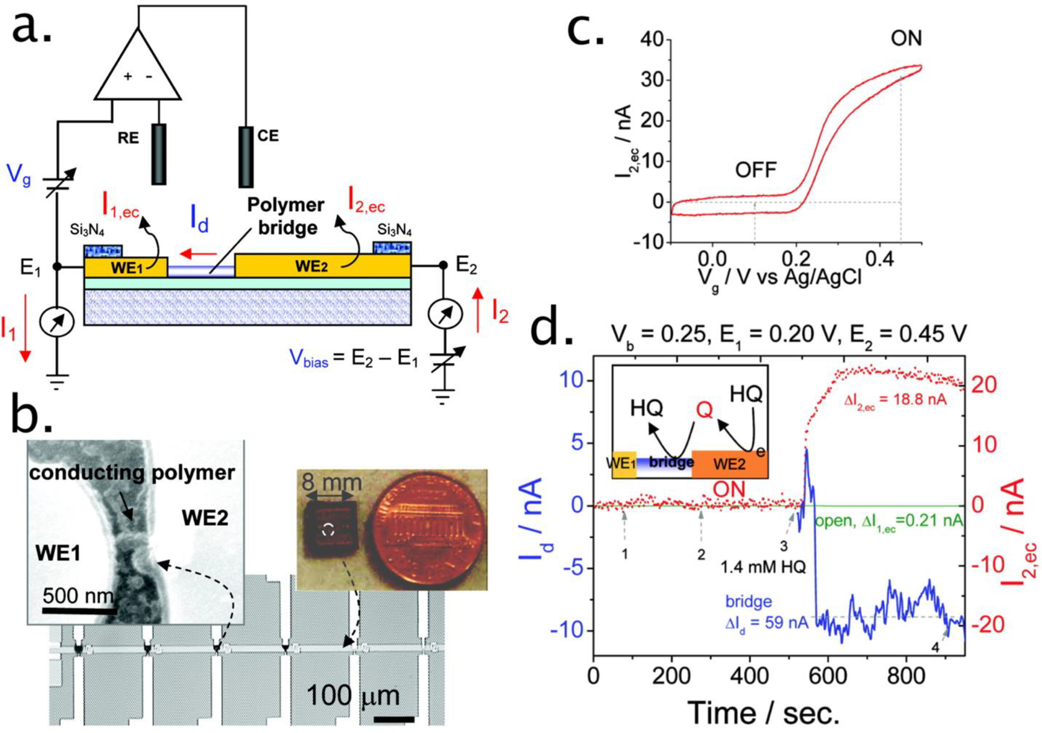
Figure 5.

(a) Schematic illustration of a hybrid amperometric and conductometric sensor. WE1 and WE2 represent two working electrodes (source and drain electrodes) connected with a conducting polymer bridge. RE and CE are reference and counter electrodes, respectively. The electrochemical gate potential (Vg) E1 is applied between the drain electrode (WE1) and RE, and a bias voltage (Vbias) is applied between WE1 and WE2. (b) Optical and scanning electron microscope images of the device made of an array of polymer bridges on a silicon chip. (c) Cyclic voltammogram of 3.9 mM hydroquinone (HQ) on polyaniline-modified microelectrode at 60 mV/s. (d) ΔId and ΔI2,ec simultaneously recorded during the injections of supporting electrolyte (1–2) and 1.4 mM HQ (3) to a close (bridge) and open polymer bridge (open) amperometric and conductometric device. Vbias) 0.25 V and E2) 0.45 V. Inset of (d) illustrates the reaction mechanism in a close polymer bridge device. Reprinted from ref34. Copyright 2007 American Chemical Society.
