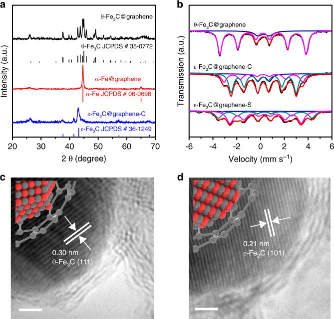
Fig. 2. Structure of θ-Fe3C@graphene and ε-Fe2C@graphene samples.
a XRD diffraction patterns for θ-Fe3C@graphene sample (black line), θ-Fe3C@graphene sample reduction under flowing H2 at 623 K for 3 h (red line), and then carbonization under flowing syngas (H2/CO = 1) at 573 K for 10 h (blue line). b 57Fe Mössbauer spectra for θ-Fe3C@graphene, ε-Fe2C@graphene-C, and ε-Fe2C@graphene-S samples. Representative high-resolution TEM micrographs for c θ-Fe3C@graphene and d ε-Fe2C@graphene-C. Scale bar, 2 nm.

