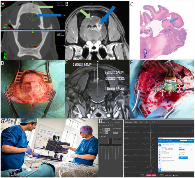
Figure 2.
(A) Targeting MRI-CT fusion- Green arrow: Plastic fiducial screw- Blue arrow: Target area (B) Radio-necrotic lesions Green arrow: left cortex—Blue arrow: right white matter (C) Histology of Necrotic lesion in white matter (D) Alignment of titanium screws on the target area. (E) Calculation of the target on the contrast MRI. (F) Inserting and fixating the probe and Omnetic connector (G) The Jumpers are connected to the head-stage connected to the PC and electrophysiology devices and the animal is under the faraday cage. The electrophysiologist is communicating with the surgeons and controlling the electrophysiology software remotely (Photo by Tonny Foghmar). (H) Screenshot showing a schematic of the BCI chip implanted in the visual cortex and the stream of the electrophysiological activity in the Allego software with TeamViewer on top.

