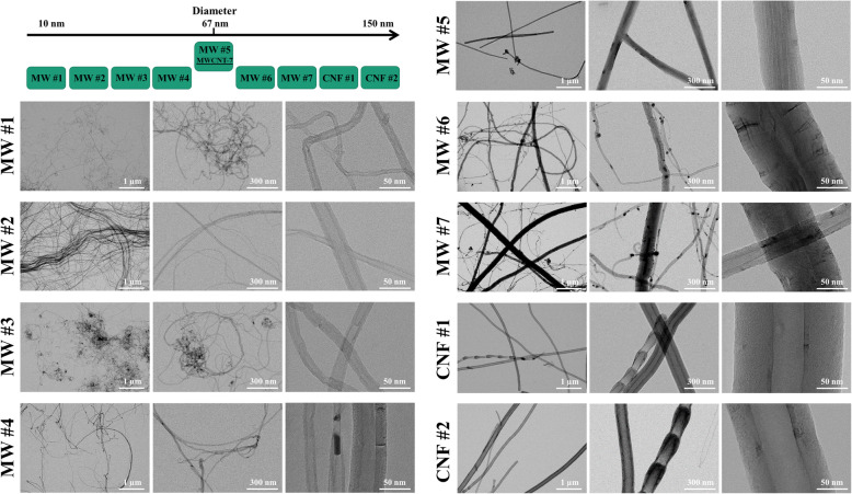
Fig. 1.
Schematic of material diameter and TEM images of CNT/F. Materials selection was based upon company reported diameter ranging from 6 to 150 nm in diameter to ensure a full range of materials were included in this study and the material arrangement is depicted in the upper left corner. These materials were identified as MW #1–7 and CNF #1–2. A well-studied benchmark material, MWCNT-7/Mitsui-7, was included in this study as MW #5. Materials were dispersed in isopropanol and placed onto a TEM grid to measure physical dimensions. Representative images of each material were selected with scale bars representing 1 μm, 300 nm, and 50 nm from left to right

