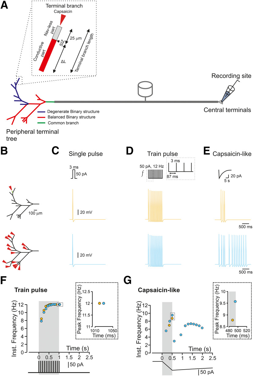
Figure 1.
The response of a nociceptive neuron to a capsaicin-like current depends on the morphology of the nociceptive terminal tree. A, Scheme depicting the model of the primary nociceptive neuron. The peripheral terminal tree morphology is rendered from the structure of a terminal innervating glabrous skin of mice paw in vivo. The terminal tree consists of 14 terminal branches of different lengths. Inset, Functional organization of a terminal branch. The first 25 µm of each terminal branch does not express Navs (Nav-less, light gray). The Nav expression starts from the SIZ and continues for the rest of the fiber (conductive part, red). The terminal branch length is defined by the length of the conductive part, which differs among the terminals and the Nav-less part, which has a constant length of 25 µm. The complex terminal tree morphology consists of the simplified version of the balanced binary tree (red terminal branches), in which two branches converge into one node (convergence point) and a degenerate binary tree, in which one branch converges into the fiber (blue terminal branches). The terminal branches converge into the mother branches, which then converge into the common branch (green branch). The stimulations are applied to the terminal branch end (red arrow in the inset), and the recording electrode is placed at the central terminal. B, The locations of the stimulations. The stimulated terminal or all terminals are marked by the red arrows, and single stimulated terminals are color coded. C, D, Simulated voltage-clamp recordings from a central terminal following stimulation of a single terminal (yellow) and all terminals (light blue) by a single brief 3-ms square current of 50 pA (C) or train of brief 3-ms square current of 50 pA applied at 12 Hz (D). Note, no difference in firing between stimulating one or all terminals. E, Same as C, but the terminals are stimulated by simulated capsaicin-like current (see Materials and Methods). Note that in this case, the firing following stimulation of one terminal differs from the firing resulting from stimulation of all terminals. F, Instantaneous discharge frequencies following stimulation with a train of brief 3-ms square current of 50 pA applied at 12 Hz (lower inset) of a single terminal (yellow), and all terminals (light blue). Shadowed area outlines the time of the stimulation. Note, no difference in peak instantaneous frequency (upper inset). G, Same as in E but following stimulation with a capsaicin-like current (color coded as in E). Shadowed area outlines the 500 ms of a capsaicin-like current step. Note, an increase in peak instantaneous frequency when all the terminals are stimulated (upper inset, light blue).

