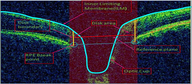
Fig. 2.
OCT image ONH centered and showing how to find the CDR by locating the cup and disc border. ILM layer and RPE layer endpoints are marked with blue line and blue circle, respectively. Reference plane (blue line) has been constructed by joining the endpoint of RPE layer; disc boundary was highlighted (yellow line); thus, the length of plane is referred as disc diameter. Cup edges are the intersection point of ILM layer and reference plane (moved 150 μm upward shown in red line); red portion represents the rim area [10]

