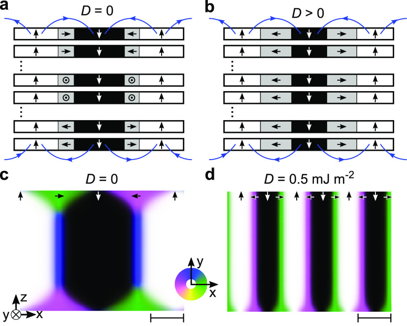
Figure 2.
(a, b) Schematic representation of the magnetic texture in FGT, showing a side view of six FGT layers. The white and black area correspond to up and down magnetized domains, and the grey areas correspond to an in-plane magnetization, with the arrows denoting the direction. The blue arrows indicate the dipolar fields. With SEMPA only the top layer of FGT is imaged. In panel (a) the DMI is zero and the magnetization in the domain walls aligns with the dipolar fields, resulting in clockwise Néel domain wall in the top layer, Bloch walls in intermediate layers, and a counterclockwise Néel wall in the bottom FGT layer. In panel (b) the DMI is positive in each layer and large compared to the dipolar fields. The magnetic texture consists of an out-of-plane rotating spin spiral in a counterclockwise direction throughout all FGT layers. (c, d) Side view of micromagnetic simulation results for 128 layers of FGT and K = 40 kJ m–3. The in-plane magnetization direction is indicated by the color wheel in the xy-plane. In (c) D = 0 and in (d) D = 0.5 mJ m–2, and for the top FGT layer a clockwise and counterclockwise rotating spin texture is found, respectively. The scale bars on the lower right hand side indicate 25 nm.

