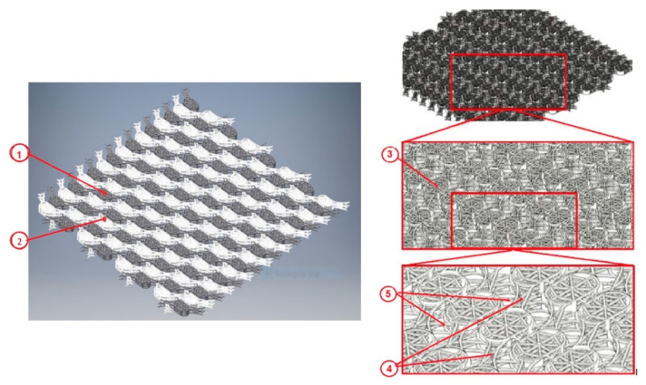
Figure 7.
Interconnected layers of the modular system. Left panel-The fixed layer ① is assembled with the movable layer ② so that translations can be performed in the Ox and Oy directions, while maintaining the position of the layer ①. Right panel-The component elements of the cranial prosthesis presented in isometric view, consisting of four basal cells defined in two constructive forms ③, the rigid connecting bridge ④ and the flexible connecting bridge ⑤.

