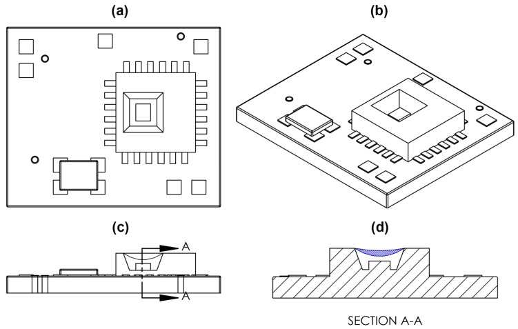
Figure 3.
Sketch of FXTH87 on custom PCB. (a) Top view of FXTH87 and PCB. (b) Isometric view of FXTH87 and PCB. (c) Side view of FXTH87 and PCB. The Capacitive transducer membrane is defined by the concave line above the rectangular box, which depicts the location of the capacitive transducer. (d) Cross section view of the FXTH87 and PCB. Blue hatched region depicts the volume filled with Sylgard 184 on the surface of the capacitive transducer membrane.

